
—————————-Phase#1: Week 12 (4/13 – 4/19):——————————————–
Name: Christopher Barry
Contribution: Power System
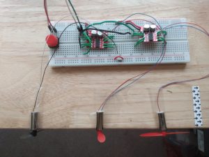
Details: This week, I tested the power system with the H-bridge motor circuit. Due to the back emf of the motors, as the more motors were added to the circuit, the supply voltage dropped. All the motors we able to run as planned for every duty cycle. Since we are relying on a 5 volt supply to power the raspberry pi, I changed the power system circuit to allow for these voltage drops. Now there are two voltage regulators connected to the power supply in parallel. One output is for the pi which will have a constant 5 volt supply. The other output will just be connected to the H-bridge circuit which will have voltage drops.
Throughout the semester, the main focus of the power system was to maximize the longevity of the operating time of the umbrella while trying to keep the component’s prices down. I originally based the circuit design off a generic diode circuit for solar panels and rechargeable batteries. The diode circuit served two purposes: to choose which power supply was supplying the most voltage and use it to power the umbrella, and to use extra power from the solar panels to recharge the batteries while in operation. A 5 volt voltage regulator was implemented into the design in order to power the raspberry pi with safe voltage and current values. After further research I faced my first problem which was that the extra power from the solar panels would not be able to charge the batteries. The diode circuit I originally looked at was a design for only one rechargeable battery. Since we have two batteries in series, the node connecting the two batteries would have both a positive and negative lead connected to it. A potential solution to this is using a battery management system (bms) board. This allows multiple batteries in series to be charged at the same time while in operation. The reason this bms design wouldn’t work is because the solar panels don’t supply enough current required for the bms boards to operate. Thus, a diode circuit was still implemented to use the solar panels instead of the lithium ion batteries to power the umbrella when possible, but they weren’t able to charge the batteries as well. This would result in a slight decrease of the longevity of the umbrella’s run time, but didn’t hinder the overall operation of the power system. Another problem I faced was deciding whether to regulate the voltage of the solar panels and batteries independently, then compare them for the power supply, or to compare the two voltages, then regulate the voltage to a safe level for the raspberry pi. At first I assumed the first option would be better since the solar panels could still potentially be used if the output voltage was in the range of 5 and 7.2 volts. But if the solar panels were first compared to the batteries’ constant 7.2 volts, the solar panels would not be used when the output voltage was less than 7.2 volts but still greater than the required 5 volts. The flaw in this design is that the compared regulated voltages would both have the same value, thus I couldn’t say for certain whether the solar panels or batteries will power the umbrella. So the final design first compares the original voltage values, determines which is greater, then regulates it down to power the umbrella. After testing, this didn’t seem like a major issue since even on an overcast day, the output voltage of the solar panels was about 8.1 volts which is greater than the batteries’ 7.2 volts. The last problem that was faced was that the motors in the H-bridge circuit dropped the voltage supply while in operation. In order to get around this, a second voltage regulator was connected to the power supply in parallel which was used to run the H-bridge circuit independently of the power supply to the raspberry pi.
Name: Jason Schwarzwalder
Contribution: Raspberry Pi Control System
Details: I have learned quite a lot from my portion of this senior design project. Before I was assigned my portion of the project, I had worked minimally with Raspberry Pi products. The last time I had used a Raspberry Pi was during freshman year for intro to engineering. We needed to move water in specified amounts to certain locations. At the start I was not familiar with what I needed to do to get a Raspberry Pi up and running. Getting the Pi setup correctly was the hardest part for me. The operating system that is recommended for first time users is NOOBS. Its designed to be as easy as possible to setup. However, I quickly realized that it had way too much stuff that I did not need. I then decided on a minimal install of Raspbian. This minimal install is terminal only, which required me to reteach myself the terminal based commands. Once I had the Raspbian installed the second big problem showed up. We had decided on the Pi-Zero. This is not the same as the Pi-Zero W. The W has access to WIFI. I ended up having to use one of my roommate’s Pi 3. He also helped me get our House WIFI setup onto the Raspbian distribution.
With the Pi finally able to access the internet I was able to start work toward coding the control system. I watched many videos and read many tutorials on how to code the Pi and the multiple different components we were going to attach to it. The DHT11 was the first thing that I coded. I felt that I should do it first because the output of this sensor was going to determine how the other components respond. The DHT11 can only send data out every 3 seconds. This was not actually hard to account for at all. However, my DHT11 usually fails to send data out 2/10 times. This was annoying to find out considering I had read good things online about the DHT sensors. I worked around that issue and moved onto the motor. The motor requires pulse width modulation as well as a transistor. Its not safe to just turn the motor to 100% and 0% as that can cause permanent damage. PWM stops the damage from happening. The transistor was necessary because the motor can cause damage to the GPIO pins if connected directly to them. The transistor is used as a switch to let current flow through the motor without being directly connected to the GPIO. The last component was the water pump. The hardest problem to overcome with the pump was not being able to determine how much water is in the sponge. This was a problem that I had trouble with for a while. A solution did finally present itself. If we connect the sponge to input and output GPIO pins we can then run electricity through the sponge. If the sponge is wet enough then electricity will flow, and the input will be high. If electricity does not flow, then we need the pump to turn on. This solution works well, but one issue I ran into is that sometimes the electricity fails to go through even if the sponge is wet. To help remedy this issue I made it so the pump will only turn on if electricity fails to go through a certain number of times. This stops the pumps from turning on in the case where the sponge is wet enough but electricity still did not go through for some reason.
Name: Jaime Martinez-Diaz
Contribution:Cooling System
Details: I changed the way in which the PWM signal was sent to the H-bridge driver circuit to a hardware signal. This surprisingly fixed the previous issue of reducing the supplied voltage and now operates in stable manner. After testing different driving frequencies to determine which reduced the noise emitted by the motors, the chosen frequency was 300Hz with the duty cycle locked at 20% to reduce power consumption.
Lessons Learned: Throughout this project I was able to apply some concepts learn in lectures, especially with creating a PWM signal to drive the H-bridge. The most important lesson learned is that implementing a design is much harder than expected. There are issues that may never come to mind in the design stage that could lead to setbacks when trying to implement your design. An example would be the water splitter, where the water coming out of each tip was not equally distributed. In the labs, thermal performance and heat dissipation were never considered, but this is an important concept to understand when power-hungry components are placed in an enclosure.
Name:Yunke Chen
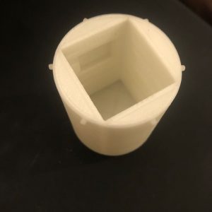
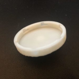
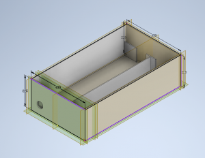
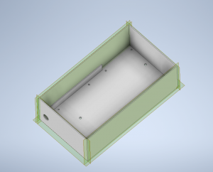
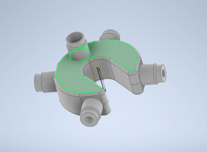
Contribution Part: umbrella ferrule
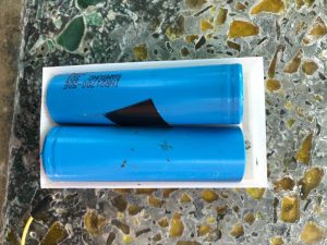
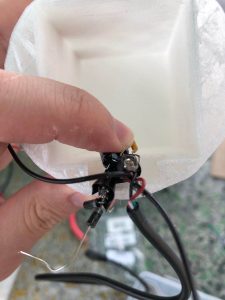
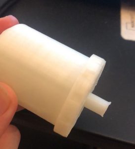
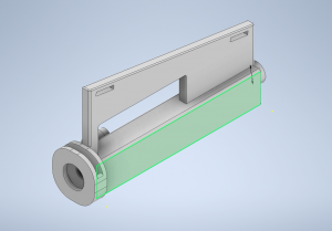
Details: I was able to redesign the final version of the ferrule that meets the power system requirement, which has two spaces to contain two voltage regulators. Both cases inside of the ferrule also ready to use. The battery case has been soldered with 3 separate metal strips which provide a better connection comparing with metal spring.
Lessons Learned: During the period of project senior design, I think I learned something beyond the regular classes. The things I learned can be contribute into 3 categories: foreseeability, the ability of coordination, and improvement of personal skill. As a project manager, I did a really bad job at the beginning. The lack of communication makes the weak info transparency between my team and our faculty supervisor. It reminds me there is a huge difference between team communication and individual one. Now, I know how important to reply to emails on time and the advantage of cc others. What’s more, I learned more about forseeability. When we order design components, we may order more than the numbers of design required, so that we have extra components to assemble in case we broke some that need to reorder. In the aspect of personal skill, I learned how to design 3D modeling by using Autodesk series software and practiced them frequently. For the 3D print, I learned that different printing material will influence the final product’s durabilities as well.
Name:Yizhe Wang
Contribution Part: Cooling system
Details: This week, I used hot melt glue to fill the gap between the atomizer and the case. It is used to prevent water from leaking out from the humidifier case. The result is not as good as I expected. The space between the humidifier and the case is too small to make the glue flow in. And it is needed to control the amount of glue that is used since too much glue can block the humidifier or reduce its vibration. The only way to prevent water from leaking is reducing the amount of water that is sent to the case.
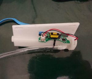
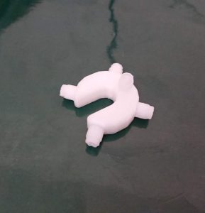
Lessons learned: Through this semester, I chose, bought, and tested many components and designed some components, including mini motors, humidifiers and water pumps. Most of them don’t have a detailed data sheet with them and we have to figure out their properties based on our experience and through testing. Through our test, we found that the humidifier cannot run if it is connected directly to the Raspberry Pi. A control board that is used to create a high-frequency signal with an amplitude about 25V is required. Because of this, we have to redesign our circuit with the control board. The motors and the water pump also need control circuits. We conceived a plan using H-bridge and another plan using transistors. Many components cannot be directly connected to the Raspberry Pi. Some of them consume a large amount of energy and require large current (like motors), others need high voltage (like humidifiers), which GPIO is not able to provide. A control circuit gets power from the power supply and tunes the components based on the signal from GPIO. A complete circuit is not enough to make the system perform, support from hardware is needed. Since the hardware on the market cannot satisfy our requirements, 3D modeling is necessary in this case. I got some experience in 3D modeling this semester. I learned how to use Autodesk Inventor to design 3D models and how to print them. Using different 3D printers may cause differences in the 3D models. The very first 3D model I got has a very nice quality and can contain water without any leakage. But after the university is closed, these 3D printers are no longer available. The 3D model made by the printer that I used afterwards was not as good as I expected. This causes a problem in containing water, and I tried many ways to solve this problem including improving the design. From this experience, I learned that using a 3D printer with a good print quality is important if the printed components are expected to contain liquid. I also designed a water splitter. Its first model failed to provide the same amount of water for four humidifiers. In the improved version, the radius of four water outlets is reduced to half of the radius of the water infall. Thus, the total cross-sectional area at the outlet is the same as the infall cross-sectional area.
Name: Christopher Aitken
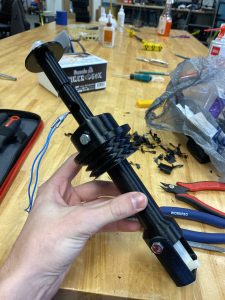
Contribution: Umbrella Handle and Water Bottle
Details: I finished 3d printing all the parts of the water bottle and the handle. I preformed some basic durability testing with the water bottle and the design held up. I did have to modify some of the parts after they were printed like the threading to get the parts to fit better. I did this through filing down some of the parts which would not affect the structural integrity.
Lessons Learned: Throughout senior design I can separate everything I learned into two categories. The first category is the physical skills and knowledge I learned from. More specifically my part of the project dealt with a lot of 3d printing and design in which I had some prior knowledge in however, I was able to learn a lot more in detail of the attributes of different filaments and all of the setting of the 3d printer and how each one can effect the print. In addition, I learned more in depth of how a humidifier works and a better understanding of how integration works with multiple parts of the project. The second category is the more intangible skills that I learned. This includes working with a team and setting goals and meeting those goals. I think this is the more important category of the two and I believe this is the real purpose of doing this project. I have learned the importance of good leadership and choosing a good group leader and I believe I have learned better ways to communicate with people in the group that doesn’t cause any tension or unneeded stress.
—————————-Phase#1: Week 11 (4/6 – 4/12):——————————————–
Name: Christopher Barry
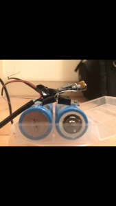
Contribution: Battery and solar panels
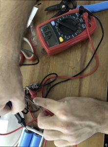
Details: Over the weekend I tested the regulated output voltage and current of the battery within the battery pack. The output voltage was 4.99 volts and the current was measured to be 20mA for a 220 ohm resistor. The ideal current is 22.6mA for this voltage and resistance. There were some connection issues with the battery pack so the values only appeared when the batteries were held in contact with the springs. The solar panels have been soldered together. On Tuesday I will test that the batteries and the solar panels can supply enough current to power the H-bridge for the motors. If all goes well, I will then attach the full power system to the umbrella.
Name: Yizhe Wang
Contribution Part: Cooling system hardware design
Details: Redesigned and tested the new humidifier case and fan case. The new humidifier case was tested to hold the atomizer better, and it makes it easier for the user to replace the cotton part. and for the fan case, I raised its hight so it is safer than the first version. Since the hot glue is not delivered, I didn’t test its water-proof ability.
Name:Yunke Chen
Contribution Part: umbrella ferrule
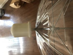
This week, I had a chance to assemble the ferrule on the umbrella. The connection part fits well. However, The battery case and wire hole are still not big enough. The connection of batteries was weak, and easy to disconnect. For next week, I may finalize the battery case’s design to let the case more stable inside of ferrule and enhance the connection of the batteries.
Name: Jason Schwarzwalder
Contribution Part: Raspberry Pi Control System
Details: I wanted to refactor the code last week. I spent some time changing it to be ‘better’. After changing it, I ended up breaking the code and it no longer worked. I had to then go back to a previous version I was using. The code works again but its not as pretty or clean as I would like.
Name: Jaime Martinez-Diaz
Contribution Part: Cooling System motors
Details: I am still working on determining the issue for the significant voltage drop from the power supply when using the H-bridge circuit. I have attempted different PWM frequencies but no improvements were made in the operation of the circuit. I have tested the circuit with a resistor in place of the motor, the results from the test show a smaller voltage drop than the motor in which the input voltage was 4.8V dropped to 4V. The current draw from the resistor at the output was 0.27A at 2.3V. Where the voltage drop of power supply from the motor was down to 3.2V instead. This voltage drop from the motor is most likely due to the back emf of the motor, in which the drop in voltage from the power supply should be expected, however, I am not certain how this will affect the entire circuit once it is connected.
—————————-Phase#1: Week 10 (3/30 – 4/5):——————————————–
Name: Jason Schwarzwalder
Contribution: Raspberry Pi Control System
Details: I was not able to spend as much time on the pi this week as I wanted to. The code works for the purposes that we need it to. I planned to refactor the code. Other things came up that got in the way. I still want to refactor it and this will be what I plan to do next week.
Name: Christopher Aitken
Contribution: Umbrella Handle and Water Bottle
Details: I redesigned some aspects of the handle design to work better with wiring wires and tubing for our design. In addition I am currently in the middle of trying to 3d print the major components such as the water bottle so we can get a finished design together. Then the next step will be to fix any flaws that might occur during construction.
Name:Yunke Chen
Contribution Part: umbrella ferrule
Details:
The ferrule’s battery case has been tested. However, it not physically fit with the battery due to the printing scaling error. Also, the power cable hole is too small to contain four wires and one raspberry pi power cable. For the ferrule top, the diode circuit needs more space to hold as well. This week, I will redesign the dimension to finalize the ferrule design.
Name:Jaime Martinez-Diaz
Contribution Part: Cooling System Motor Control
Details:
Testing the motor control using the voltage regulator was performed over the weekend. Having the H-bridge power input directly connected to the NTE 960 voltage regulator reduced the voltage supplied by the voltage regulator and resulted in poor performance from the motors. This abnormality of reducing the supplied 5V has not been resolved. From testing the current draw of a single H-bridge controlling two motors at 100Hz, 25% duty cycle, is 146mA. The used voltage regulator can supply 1A; further testing will be performed to correct this issue.
Name: Yizhe Wang
Contribution Part: Cooling system hardware design
Details: testing the water splitter under the water tap and the plastic tubes and testing the humidifier case with water tap and the plastic tubes. The result shows that the water splitter can provide water equally when it gets water from the water tap. For the humidifier, I tested the tightness again and it shows that it is the connection of humidifier components and the case where the water leaks. Thus, I plan to have some hot melt glue on the connection of humidifier components and the case to prevent the leakage
Name: Christopher Barry
Contribution Part: Power System
Details: I planned on testing the output voltage and current from the voltage regulator (NTE 960) over the weekend. Though, the batteries seemed to be dead during the testing. Also, the batteries wouldn’t fit in the case. The batteries have since been charged and in the next few days I will meet with Chen to attach them to the slightly larger battery case and solder the diode circuit to the case.
—————————-Phase#1: Week 9 (3/23 -3/29):——————————————–
Name:Yunke Chen
Contribution Part: umbrella ferrule
Details:
For now, I have finished the ferrule part which includes the ferrule top, ferrule connection, batteries case, and control board case. I printed a 60% scaled version demo for testing. The whole ferrule works fine. Next week, I will redesign the batteries case and ferrule for the battery’s circuit add-on. Also, I will work on the connection between the top and bottom, trying to make it stable and easier to handle.
Name: Yizhe Wang
Contribution part: Cooling system components design
Details: I made and improved the 3D model of humidifier holder and water splitter. I printed them in full scale and tested them. for the humidifier case, the control board and the atomizer fit in the case well. But it still needs to be improved since water may spill over in some cases.
Name:Christopher Aitken
Contribution Part: Umbrella Handle and Water Bottle
Details: I printed out most of the umbrella handle and made small modifications to the design of them for it too work better. In addition, the water bottle is designed but not printed out yet and will try to get it printed out as soon as possible.
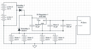
Name: Christopher Barry
Contribution Part: Diode Circuit
Details: I designed and soldered a diode circuit that compares the voltage of the batteries and the solar panels. Whichever voltage is greater will become the input to the voltage regulator which will drop the voltage to 5 volts to safely power the Pi Zero. Electrolytic and ceramic capacitors were used to keep a constant and stable output. The circuit dimensions were measured in order to design the ferrule to fit the circuit. There are currently 4 open wires: A voltage input for the batteries and solar panels, and a ground for the batteries and solar panels. The next step is to attach the solar panels to the umbrella canopy and connect them and the batteries with wires of appropriate length to the diode circuit.
Name: Jaime Martinez-Diaz
Contribution: Cooling system Fan Control
Details:Developed control for the four fans that will be incorporated in the Umbrella using the Raspberry Pi 3. The four fans are controlled with two H-bridge driver circuit boards and a PWM signal is sent via the Pi’s pinout. The PWM signals are developed through software, instead of timers with the help of a soft PWM library.
Name: Jason Schwarzwalder
Contribution: Raspberry Pi Control System
Details: I developed and tested the code to detect the amount of water in the sponges. Using two pins, one input and one output, the pi will attempt to run electricity through the sponge. Even when the sponge is damp the pi sometimes fails to send electricity through the sponge. To combat this issue the pi will sample the output over a period of time. It then figures out if the sponge has an acceptable amount of water in it and will turn the water pumps on accordingly.
SAMPLE:

Name:
Contribution Part:
details...